TABLE OF CONTENTS
- 1. Safety Instructions
- 4. Installation
1. Safety Instructions
Statement
Before transporting, storing, installing, operating, using or maintaining the equipment, read this manual first and follow the instructions strictly. Follow all safety precautions marked on the equipment and in this manual.
The "Danger", "Warning" and "Notice" items in this manual do not represent all safety items that must be observed. You must also comply with relevant international, national or regional standards and industry practices. The company does not assume responsibility for violations of safe-operation requirements or of design, production and usage safety standards.
This equipment must be used in an environment that meets its design specifications. Otherwise, resulting failure, malfunction or component damage is not covered by the equipment warranty, and the company is not liable for personal injury or property loss. All operations — transportation, storage, installation, operation, use and maintenance — must comply with applicable laws, regulations, standards and specifications.
The company shall not be liable for any of the following circumstances or their consequences:
- Damage caused by earthquake, flood, volcanic eruption, mudslide, lightning strike, fire, war, armed conflict, typhoon, hurricane, tornado or other extreme weather;
- Operation outside the conditions of use described in this manual;
- An installation or use environment that does not comply with relevant international, national or regional standards;
- Installation or maintenance performed by unqualified personnel;
- Failure to follow the operating instructions and safety warnings in the product and documentation;
- Unauthorized disassembly or modification of the product, or modification of software code;
- Damage caused during transportation by you or a third party you entrust;
- Damage caused by storage conditions that do not meet the product documentation requirements;
- Materials and tools that do not meet local laws, regulations and relevant standards;
- Damage caused by your or a third party's negligence, intent, gross negligence or improper operation, or other reasons not attributable to the company.
1.1 Personal Safety
————————————————————————————————————————
![]() Danger:
Danger:
Working with power on during installation is strictly forbidden. Never install or remove cables while energized — arcing or sparking at the cable core can cause fire or personal injury.
————————————————————————————————————————
![]() Danger:
Danger:
When the equipment is energized, irregular or incorrect operation may cause fire or electric shock, resulting in personal injury or property loss.
————————————————————————————————————————
![]() Danger:
Danger:
During operation it is strictly forbidden to wear watches, bracelets, rings, necklaces or other conductive objects — risk of electric shock and burns.
————————————————————————————————————————
![]() Danger:
Danger:
Use dedicated insulated tools for all operations to avoid electric shock or short-circuit faults. The insulation withstand-voltage rating must meet local laws, regulations, standards and specifications.
————————————————————————————————————————
![]() Warning:
Warning:
Personal protective equipment must be used during operation: protective clothing, insulating shoes, goggles, safety helmet, insulating gloves, etc.
————————————————————————————————————————

Required personal protective equipment
1.1.1 General Requirements
- Do not disable equipment protection devices.
- Do not ignore the warnings, cautions and precautions in the manual and on the equipment.
- If any fault that may cause personal injury or equipment damage is found during operation, stop immediately, report to the person in charge, and take effective protective measures.
- Do not power on the device before it has been installed and checked by professionals.
- Never touch power-supply equipment directly, through other conductors, or via wet objects. Before touching any conductive surface or terminal, measure the voltage at the contact point to confirm there is no risk of electric shock.
- Never touch a running fan with fingers, parts, screws, tools or boards — risk of hand injury and equipment damage.
- If a fire occurs, evacuate the building or equipment area and call the fire alarm. Never re-enter a burning building or equipment area under any circumstances.
1.1.2 Personnel Requirements
Only professionals and trained personnel may operate the equipment.
Professionals: familiar with the principles and structure of the equipment, experienced in operating it, and aware of the sources and magnitude of potential danger during installation, operation and maintenance.
Trained personnel: have received appropriate technical and safety training, have the necessary experience, are aware of the dangers a given operation may pose to them, and can take measures to minimize danger to themselves and others.
- Personnel installing and maintaining the equipment must first undergo rigorous training, master the correct operating methods, and understand all safety precautions and relevant standards of their country/region.
- Only qualified professionals or trained personnel may install, operate and maintain the equipment.
- Only qualified professionals may remove safety facilities or debug and repair the equipment.
- Personnel performing electrical work, work at height, or special-equipment operations must hold the special operation qualifications required locally.
- Replacement of equipment or parts (including software) must be performed by authorized professionals.
- No one other than operating personnel may approach the equipment.
1.2 Electrical Safety
————————————————————————————————————————
![]() Danger:
Danger:
Before making electrical connections, make sure the device is intact and undamaged — otherwise electric shock or fire may result.
————————————————————————————————————————
![]() Danger:
Danger:
Irregular or incorrect operation may cause accidents such as fire or electric shock.
————————————————————————————————————————
![]() Warning:
Warning:
Prevent foreign objects from entering the equipment during operation — they may cause short-circuit faults, damage, reduced load power supply, power failure or personal injury.
————————————————————————————————————————
![]() Warning:
Warning:
When installing equipment that needs grounding, install the protective ground wire first. When dismantling, remove the protective ground wire last.
————————————————————————————————————————
![]() Notice:
Notice:
Because of corrosion between copper and aluminum, direct connection of aluminum wire is strictly forbidden.
————————————————————————————————————————
1.2.1 General Requirements
- Installation, operation and maintenance must follow the order of steps in this manual. Do not modify, add to or change the equipment, or change the installation sequence, without authorization.
- Install temporary fences or warning ropes around the work area and hang a "No Entry" sign. Non-staff are strictly prohibited from entering.
- Before installing or removing power cables, the device itself and its upstream and downstream switches must be disconnected.
- The charging station must reserve enough power-access load capacity for the equipment; AC input voltage and current must meet the technical parameter requirements.
- In an emergency, press the emergency stop switch immediately and disconnect the upstream switch. Do not perform other operations — contact professionals.
- If liquid enters the device, turn off the power immediately and do not continue using it.
- Before working on the equipment, check that tools meet requirements and register them; after work, collect them by count so none are left inside the equipment.
- Before installing power cables, confirm cable labels are correct and cable terminals are well insulated.
- Use a torque tool of suitable range to tighten screws. Keep the wrench straight; torque error must not exceed 10% of the specified value.
- Mark tightened screws with a red marking line crossing the screw edge after the installer and inspector have both confirmed tightness.
- Ensure all air ducts function properly, control electromagnetic interference, and prevent dust or other foreign matter from falling on internal components and boards.
- After installation, ensure all protective covers, insulating sleeves and similar devices are in place to avoid electric shock risk.
- After installation, promptly clean up tools, metal parts and debris in and around the device.
- If the device has multiple inputs, disconnect all inputs and operate only after the device is completely powered off.
- When maintaining downstream power-consumption or distribution equipment, turn off the corresponding output switch of the power supply equipment.
- When maintaining the equipment, disconnect the upstream switch or breaker, hang a "Do Not Close" sign on it, and post warning signs to prevent accidental reconnection. Power on again only after the fault is resolved.
- Power-outage troubleshooting sequence: power outage → electrical test → installation of grounding wire → hanging signs and installing barriers.
- Check terminal screws regularly to make sure they are tight.
- Damaged cables must be replaced by a professional.
- Never alter, damage or cover logos and nameplates on the equipment. Replace unclear logos in time.
- Do not use water, alcohol, oil or other solvents to clean electrical components inside or outside the equipment.
1.2.2 Grounding Requirements
- Grounding impedance must meet local electrical standards.
- The equipment must be permanently connected to protective ground. Before operating, check the electrical connections to confirm reliable grounding (grounding resistance ≤ 4 Ω).
- Do not operate the equipment without a grounding conductor installed.
- Do not damage the grounding conductor; confirm grounding continuity before relying on it.
- For devices using three-pin sockets, ensure the socket's grounding terminal is connected to protective ground.
- This is a large contact-current device. Before connecting input power, ground the protective grounding terminal of the housing to prevent leakage current causing electric shock.
1.2.3 Wiring Requirements
- Cable selection, installation and routing must comply with local laws, regulations and specifications.
- Never form loops or twists when laying power cords. If a cord is too short, replace it — joints or welding points in power cords are strictly forbidden.
- After cables are split, protect the cable terminals at the split points.
- All cables must be securely connected, well insulated and of appropriate specification.
- Cable troughs and wire holes must have no sharp edges; protect conduits and holes so cables are not scratched or damaged by edges or burrs.
- Bundle same-type cables together, straight and neat, with undamaged sheaths; lay different cable types separately, never entangled or crossed.
- After commissioning, immediately seal cable openings with fireproof mud to keep out moisture and small animals.
- Fix buried cables securely with brackets and clamps. Cables in back-fill areas must contact the ground closely to prevent stress damage during back-filling.
- If external conditions change (laying method, ambient temperature), re-verify cable selection and current-carrying capacity per local regulations.
- Never push cables directly off the vehicle or perform similar irregular handling — damage degrades current-carrying capacity and temperature performance.
1.2.4 Anti-static Requirements
- Static electricity from the human body can damage static-sensitive components such as large-scale integrated circuits (LSI).
- Before touching a circuit board or chip, follow electrostatic protection rules: wear anti-static work clothes and anti-static gloves or a wrist strap, with the strap's other end well grounded.
- Hold boards and modules by component-free edges only; do not touch components with your hands.
- Pack removed boards or modules in anti-static packaging before storage or transport.
1.3 Environmental Requirements
————————————————————————————————————————
![]() Danger:
Danger:
Never place or operate the device in an environment with flammable or explosive gas or smoke.
————————————————————————————————————————
![]() Danger:
Danger:
Storing flammable or explosive items in the equipment area is strictly forbidden.
————————————————————————————————————————
![]() Danger:
Danger:
Never place the device near heat or fire sources (fireworks, candles, heaters, other heating devices). Heat may damage the device or cause fire.
————————————————————————————————————————
![]() Warning:
Warning:
While the device is running, do not block or cover the ventilation openings or cooling system — high temperature may damage the device or cause fire.
————————————————————————————————————————
1.3.1 General Requirements
- Store the equipment at suitable temperature and humidity, in a clean, dry, well-ventilated area protected from dust and condensation.
- Never install or operate the equipment beyond the range of its technical specifications.
- Never install, use or operate outdoor equipment and cables (including moving equipment, plugging/unplugging outdoor signal interfaces, work at height, outdoor installation, opening doors, etc.) in severe weather such as lightning, rain, snow or wind of force 6 or above.
- Never install the equipment in environments with dust, smoke, volatile or corrosive gas, infrared or other radiation, organic solvents or excessive salt.
- Never install the device in environments with metallic conductive dust or magnetic dust.
- Never install the equipment where fungi, moulds or other microorganisms are likely to grow.
- Never install the equipment near strong vibration, strong noise sources or strong electromagnetic interference.
- Site selection must comply with local laws, regulations and relevant standards.
- The ground must be solid — no rubber soil, soft soil or soil prone to sinking. Avoid low-lying or water-accumulating areas; the site level must be above the historical high-water level.
- Before opening the door for installation, operation or maintenance, first clear accumulated water, ice, snow or debris from the top so nothing falls into the equipment.
- Ensure the installation base is sturdy and meets the equipment's load-bearing requirements.
- Seal all wiring holes: use sealing mud where cables are routed, and the supplied covers where no cables are routed.
- After installation, remove empty packaging (cartons, foam, plastic, cable ties, etc.) from the area.
1.4 Machinery Safety
————————————————————————————————————————
![]() Danger:
Danger:
When working at height, wear a safety helmet and safety belt or waist rope tied to a firm, sturdy structure. Never hook onto moving unstable objects or sharp-edged metal — a slipping hook can cause a fall.
————————————————————————————————————————
![]() Warning:
Warning:
Tools must be fully prepared and inspected by professional organizations. Do not use tools that are damaged, failed inspection, or are past their inspection validity. Ensure tools are sound and not overloaded.
————————————————————————————————————————
![]() Warning:
Warning:
The cabinet must be firmly fixed so it cannot tilt or collapse due to an unstable center of gravity, injuring installers or damaging equipment.
————————————————————————————————————————
![]() Warning:
Warning:
Drilling holes in the equipment is strictly forbidden. Drilling damages sealing, electromagnetic shielding, internal components and cables; metal chips can enter and short-circuit components and boards.
————————————————————————————————————————
1.4.1 General Requirements
- Repair paint scratches from transportation and installation promptly; never leave scratched areas exposed for long.
- Arc welding, cutting and similar operations on the equipment are prohibited without the company's evaluation.
- Installing other equipment on top of this equipment is prohibited without the company's evaluation.
- When working above the equipment, add protection on top of it to avoid damage.
- Use the correct tools and the correct techniques.
1.4.2 Lifting Heavy Objects Safely
- Be prepared to bear the weight before carrying, to avoid crush or sprain injuries.
- When several people carry together, account for height differences and distribute the load evenly.
- With two or more carriers, one person leads; lift and lower simultaneously at a unified pace.
- Wear protective gloves, work shoes and other safety equipment when moving equipment by hand.
- Get close to the object, squat down, and lift with your legs — not your back.
- Lift slowly and steadily; do not jerk or twist your torso.
- Hold the handle or support the bottom edge of the device — not installed parts or module handles.
- Do not lift heavy objects quickly above waist height. Rest them on a workbench or suitable surface at half-waist height, re-position your grip, then lift.
- Move heavy objects with balanced, steady force at a uniform, slow speed; position them steadily and slowly.
- Avoid impacts or drops that could scratch the surface or damage components and cables.
- Take special care near workbenches, slopes, stairs and slippery areas.
- At thresholds, make sure the doorway is wide enough for the equipment, to avoid crushed or scratched fingers.
- When transferring a heavy load, move your feet — do not twist your waist. Point your feet in the direction of travel first, then move.
- When using a forklift, keep the load centered on the forks to prevent tipping. Secure the equipment to the forklift with ropes before moving, and move with special care.
- For long-distance transport, choose sea freight or roads in good condition; rail and air transport are not supported. Minimize pitch and tilt.
1.4.3 Lifting (Hoisting) Safety Precautions
- Lifting personnel must be trained and qualified before taking up the work.
- Erect temporary warning signs or fences to isolate the lifting area.
- The foundation of the lifting area must meet the crane's load-bearing requirements.
- Before lifting, ensure lifting tools are firmly fixed to a fixed object or wall meeting load-bearing standards.
- During hoisting, never walk or stand under the boom or the lifted object.
- Do not drag wire ropes or lifting equipment, and do not strike them with hard objects.
- Keep the angle between the two slings no greater than 60°, as shown below.

Sling angle must be ≤ 60°
1.5 Charging Equipment Safety
1.5.1 General Notes
- When the charging device is transported alone, add appropriate protection against vibration, impact and falls.
- Do not allow children to approach, touch or use the charging station.
- Do not place flammable, explosive or combustible materials, chemicals or flammable vapours near the charger.
- Do not use the device in abnormal conditions such as water ingress or leakage.
- Do not use the charger if it is faulty. Do not act on your own if charging is abnormal — contact the staff.
- Do not disassemble, repair or modify the charger. For repair or modification, contact the staff — improper operation may cause equipment damage, water leakage or electric leakage.
- Strictly follow the charging instructions and prompts on the device — otherwise there is a risk of electric shock and fire.
- Operation and maintenance personnel must regularly inspect and maintain the emergency stop switch to ensure it works.
- In case of power failure, repairs must be performed by professionals or authorized maintenance personnel.
- In case of fire, flooding of the charging equipment or other accidents, do not approach the equipment — promptly notify professionals familiar with the equipment and emergency response.
1.5.2 Notes on Using the Charger
- This device is only for charging electric vehicles.
- When not in use, place the charging connector in its holder to avoid contamination and damage.
- Before charging, check the charging device for scratches, rust, cracks, or damage to the charging port, cable or plug. Do not use a damaged device.
- Before charging, check the charging connector, holder insulator, pins and sockets — they must be clean and free of foreign objects. If foreign objects are found, report to staff immediately; charging is prohibited.
- Before charging, make sure the connector is fully plugged in and the hook is fully engaged.
- Modifying or disassembling the charging connector, or using external cables or adapters, is strictly forbidden — it can cause charging failure or, in serious cases, fire.
- Never touch connector pins or holder sockets with sharp objects (screwdrivers, tweezers) — they damage the pins and sockets.
- Do not put your fingers into the charging plug.
- Never immerse the charging connector in water.
- Never step on or drive over the connector head or connector cable.
- Never touch the vehicle charging port during charging.
- Never remove the connector head during charging — this protects both people and the vehicle.
- During thunderstorms, stop charging — lightning may damage the charging equipment.
- In an emergency, press the emergency stop switch immediately, do nothing else, and contact professionals.
- The vehicle must remain stationary during charging. For hybrid vehicles, turn off the engine before charging.
- The charging operator must monitor the charging process. In extreme weather (typhoon, heavy rain, hail, etc.), terminate charging immediately.
- After charging is complete, never start the vehicle before unplugging the vehicle plug.
2. Introduction
2.1 Product Description
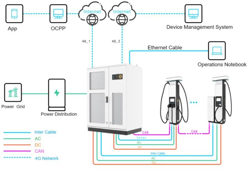
The charger consists of four main parts: AC input and protection, AC/DC conversion modules, DC output power distribution, and the control system. The DC charger supports up to twelve 300 A DC outputs and can be configured with a 300 A dual-connector terminal and a 500 A liquid-cooled terminal. A dual 4G network configuration keeps the operation platform and the equipment-management platform on independent networks, making data more secure.
System networking diagram:
2.2 Datasheet
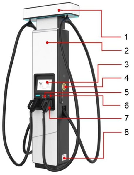
Full specifications are listed in a separate article: DC480kW Stand (Without Cooling) — Specifications [HERE]2.3 Appearance


————————————————————————————————————————
![]() Notice:
Notice:
The emergency stop button is for emergencies only — do not use it in non-emergency situations. If the protective cover of the emergency stop button is damaged after use, replace the cover.
————————————————————————————————————————


————————————————————————————————————————
![]() Notice:
Notice:
Reserve a grounding plate near the terminal grounding position during site planning and construction. When pre-burying the ground grid, the grounding plate must be long enough (extending more than 100 mm beyond the base) to ensure connection with the cabinet grounding point.
————————————————————————————————————————
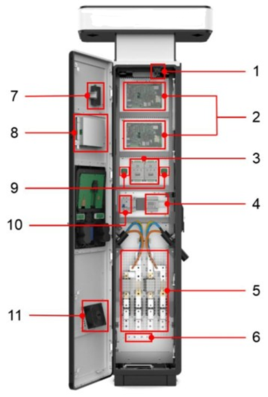
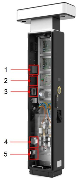
2.4 Internal Devices
2.4.1 Front Door Internal Components


3. Transportation
3.1 Labels on the Product Packaging

3.2 Transportation
————————————————————————————————————————
![]() Notice:
Notice:
Before transport and delivery, make sure you know the cabinet's dimensions, weight and transport-packaging requirements so it can be delivered safely. Refer to the cabinet parameters, arrange appropriate transport equipment, and check that the site access routes meet the space and equipment requirements for transportation.
————————————————————————————————————————
4. Installation
4.1 Installation Area Selection
————————————————————————————————————————
![]() Notice:
Notice:
Check every item against the requirements below and install only after all requirements are met. The company is not responsible for losses caused by forced installation at a site that does not meet the requirements.
————————————————————————————————————————
4.1.1 General Site Selection Requirements
- Good 4G coverage, or a wired network interface with Internet access.
- Convenient transport access and reliable fire-fighting measures.
- Sufficient site area for current needs, with room for expansion over the full life cycle.
- A well-ventilated area.
- Away from strong vibration, strong noise sources and strong electromagnetic interference.
- Away from areas that generate dust, fumes or harmful gases, and from places where corrosive, flammable or explosive items are produced or stored.
- The site power supply meets the product's technical specifications.
- A spacious site, convenient for parking EVs and for charging operations; local laws and regulations must also be considered.
- Install the charging terminal close to the charging host — the maximum wiring distance between host and terminal is 80 m.
- Reserve a grounding plate near the terminal grounding location during site planning, with sufficient length to connect to the cabinet grounding point.
4.2 Installation Requirements
4.2.1 Installation Environment Requirements
- Avoid installing below locations where objects could fall.
- Do not install in low-lying areas; the installation level must be above the area's historical high-water level.
- The soil must be in good condition and the ground solid — no rubber soil, soft soil or other poor geology. Avoid ground prone to water accumulation or subsidence.
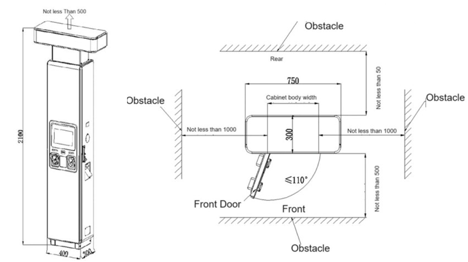
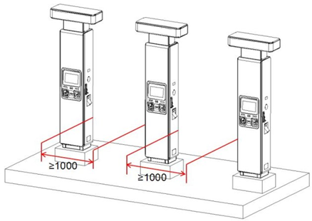
4.2.2 Distance Requirements from Obstacles
- The terminal should be installed centrally at the rear of two parking spaces.
- Installation space requirements are shown below:
4.2.3 Foundation Requirements
Construct a base on the selected ground before installing the equipment. Plan and design the base according to the installation space requirements and base dimensions, so it meets the cabinet's fixing and wiring needs.
- Recommended base height: 200 mm, to meet cabinet installation and load-bearing requirements.
- Level error of the contact surface between base and cabinet: less than 3 mm.
- The wiring area of the base must have drainage measures to prevent water accumulation.

4.2.4 Foundation Construction Requirements
- The installation location is determined by the site. After excavation, compact the foundation pit to a compaction coefficient of 0.95.
- After excavation, pre-bury the power-line conduit. Use carbon corrugated pipe, steel pipe or PVC pipe with a diameter at least 1.5× the cable outer diameter. The conduit position shown in the figure uses a direct-buried trench under the foundation as an example — adjust according to the actual cable trench position.
- Ordinary concrete: foundation Fc ≥ 14.3 N/mm², cushion Fc ≥ 9.6 N/mm²; concrete strength may be increased on site as needed.
- M12×100 embedded bolts must be perpendicular to the foundation surface with 30 mm exposed, so 3–4 threads remain exposed after the nut is tightened.
- Lay the charger's repeated-grounding flat iron along the cable trench in accordance with local laws and regulations.
- The threading sleeve extends 100 mm above the cushion layer.
- All dimensions in the figures are in mm.
- Anything not covered in the figures follows current national standards.


4.3 Installation Preparation
4.3.1 Protective Equipment

4.3.2 Handling Equipment

4.3.3 Installation Tools

4.3.4 Cable Preparation
4.3.4.1 Cable Recommendations

4.3.4.2 Cable Binding Requirements
- Bundle similar cables together. Lay different cable types (AC, DC, signal) separately — never twisted or crossed.
- AC cables, DC cables and signal cables must be bundled separately, never together.
- Bundled cables must be neatly aligned with undamaged outer sheaths.
- Cable-tie heads must face the same direction; ties at the same level must form a horizontal line.
- After installation, label or tag cables at both ends, at mid-points, or at bends.
- When trimming cable ties, leave about 3 mm and cut neatly.
- Bundle AC and signal cables inside the terminal cabinet as shown below:

4.3.4.3 Safety Requirements
- Avoid sharp objects and wall burrs when laying cables; where unavoidable, protect cables with a bushing.
- Keep cables away from heat sources, or add heat-insulation material between them, to prevent melting, aging or cracking of the insulation.
- Leave an appropriate margin (about 0.1 m recommended) at turns and near equipment, to ease maintenance of cables and equipment.
4.3.4.4 Cable Routing Requirements
- Protect outdoor cables that could be accidentally damaged — for example by placing them in conduits.
- The inner diameter of the protective tube must be at least 1.5× the cable outer diameter (including the protective layer).
- After cables are split, install cable terminals at the split points for protection.
- Lay the cables in the correct direction, then install the cable clamps.
- Power-cable routing must comply with local regulations and construction requirements.
- Power-line layout must follow the engineering design drawings.
- If a power cord is found to be too short during routing, replace it — joints or welding points in power cords are forbidden.
- Cable deployment must be strictly organized, with dedicated personnel directing and coordinating. Untrained personnel and work without communication facilities are prohibited.
- Loops and twists are strictly prohibited during deployment.
4.3.4.5 Protective Ground Cable Requirements
- Connect the protective ground wire to the ground bar; the equipment grounding overlap resistance must not exceed 4 Ω.
- Never bring the protective ground wire in via outdoor overhead routing — it must be buried underground or routed indoors for its entire length.
- Do not bundle or entangle the protective ground wire with signal wires; keep them apart to reduce interference.
- Installing switches or fuses on the protective ground wire is strictly prohibited.
- Using other equipment as part of the protective ground electrical connection is strictly prohibited.
- All accessible conductive metal parts inside the equipment casing must be reliably connected to the protective grounding terminal.
4.3.5 Protection Switch Confirmation
————————————————————————————————————————
![]() Danger:
Danger:
Before wiring, make sure the upstream switch is OFF. Connect the cabinet input and output cables first, and only then connect the cables at the cabinet's upstream power switch.
————————————————————————————————————————
Upstream switch recommendation: the front-stage AC switch of the 480 kW host can use one 1250 A frame circuit breaker, or two 630 A molded-case circuit breakers, for power distribution.
4.4 Installation Procedure
4.4.1 Cabinet Unpacking
Unpacking tools: crowbar, needle-nose pliers, Phillips screwdriver, wrench, utility knife.
4.4.1.1 Remove the Cabinet's Wooden Packaging
- Remove the wooden packaging.
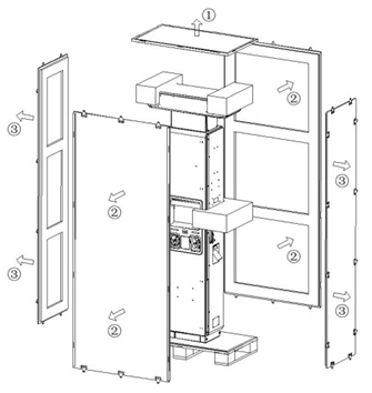
- Remove the EPE buffer blocks around the cabinet.
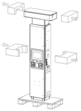
- Remove the PE bag from the cabinet.
4.4.1.2 Remove the Cabinet Base Baffle
Use a Phillips screwdriver to remove the four screws fixing the base baffle on the front and back of the cabinet. Store the screws and baffle for later reuse.

4.4.1.3 Remove the Cabinet Pallet
Use a wrench to remove the four screws fixing the wooden pallet at the front and back of the cabinet bottom, then move the pallet to the recycling area.

4.4.1.4 Remove the Protective Plate
Open the cabinet door, remove the four M4 screws and the protective cover at the incoming-line protection plate, and store them — the protection plate and screws must be reinstalled after wiring. Screw specification: M4.

4.4.1.5 Remove the Cabinet Base Cable Guard
Use a utility knife, needle-nose pliers or similar tool to cut the protective cable ring at the bottom of the cabinet along the ring texture.

4.4.2 Cabinet Installation (Placing on the Foundation)
Use a forklift or crane to place the cabinet on the cement platform.
4.4.2.1 Forklift Installation Requirements
- Choose a forklift that meets the cabinet's insertion requirements based on the cabinet's basic parameters.
- Select the correct insertion position per the pallet instructions, to avoid the cabinet tilting during insertion.
- Clear the forklift's travel route before insertion and move smoothly — excessive shaking could tilt the cabinet.
- Align the cabinet's bottom installation holes with the pre-set bolts on the base, then lower it steadily.
4.4.2.2 Crane Installation Requirements
- Choose a crane that meets the cabinet's hoisting requirements based on the cabinet parameters and the actual space on site.
- Check that the lifting rings on top of the cabinet are securely installed before hoisting.
- Tie the sling or strap firmly, with no slack; the lifting angle must be ≤ 60°.
- Consider the cabinet's center of gravity when tying the sling, so the cabinet stays stable when lifted.
- Clear the crane arm's travel route before hoisting and move smoothly — excessive shaking could tilt the cabinet.
- Align the cabinet's bottom installation holes with the pre-set bolts on the base, then lower it steadily.
4.4.2.3 Hoisting Steps
- Remove the screws and covers on both sides and store them — the covers and screws must be reinstalled after hoisting.
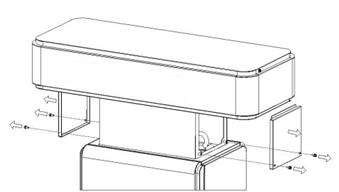
- Tie the sling or strap through the cabinet's lifting rings, pulling vertically upward.
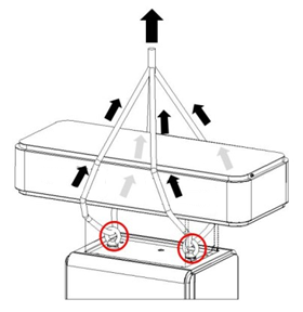
————————————————————————————————————————
 Note:
Note:Use protective pads (cardboard, foam, etc.) where the sling, strap or other load-bearing ropes contact the cabinet, to prevent friction that could cause the terminal to rust.
————————————————————————————————————————
- Split the cable before it enters the cabinet, reserving length according to the base size and the internal wiring position. During hoisting or insertion, keep the cable as vertical as possible so it enters the cabinet smoothly as the cabinet is slowly lowered.
4.4.3 Securing the Cabinet
- Clear debris from the foundation surface and confirm its flatness meets the requirements.
- Ensure the pre-embedded cables have been routed up from the base to the correct height.
- Move the cabinet above the installation carrier and align the cabinet installation holes with the bolts on the carrier.
- Pass the cables through the bottom cable-entry hole into the cabinet.
- Slowly lower the cabinet, making sure no cables are pinched or damaged, until the cabinet bottom rests stably on the installation carrier.
- Fix the cabinet with M12 nuts and washers (tightening torque: 450 kgf·cm).

4.4.4 Cabinet Grounding
After fixing the cabinet, use M8 screws to fix the grounding flat steel to the grounding seat at the right rear of the cabinet.

————————————————————————————————————————
![]() Note:
Note:
It is recommended to connect the grounding flat steel directly to the external grounding busbar.
————————————————————————————————————————
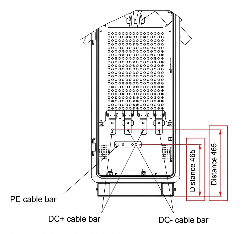
4.4.5 Cabinet Wiring
The diagrams below illustrate the wiring positions. Refer to the wiring construction manual for detailed wiring.
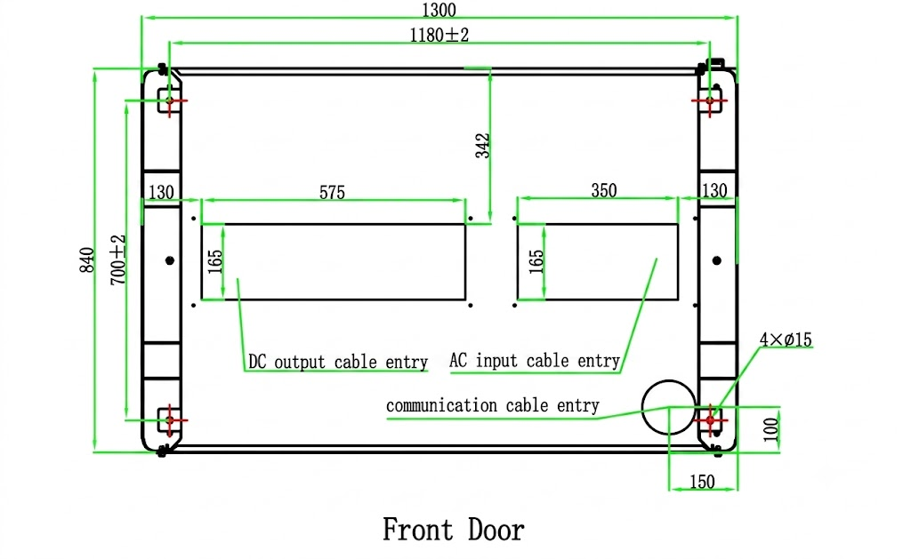
Charger cable inlet measurements
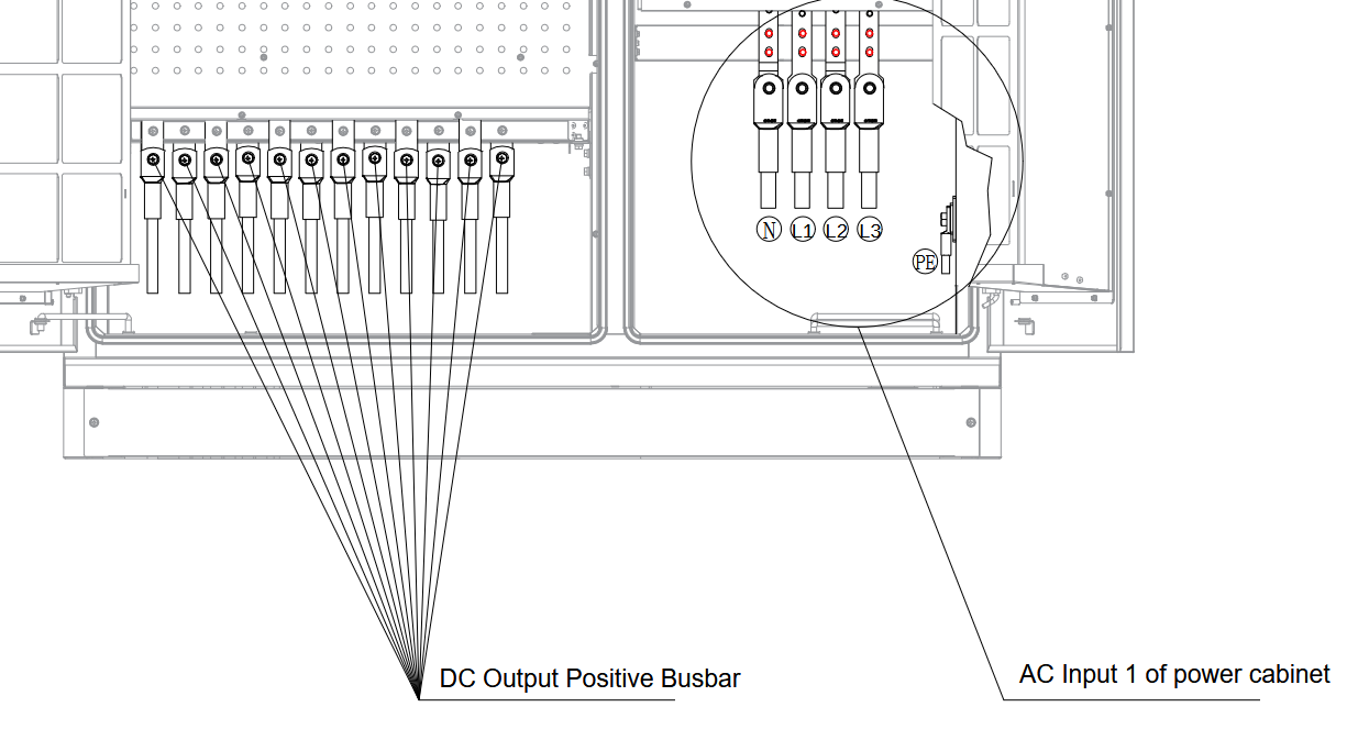
4.4.5.1 Power Input Wiring Diagram
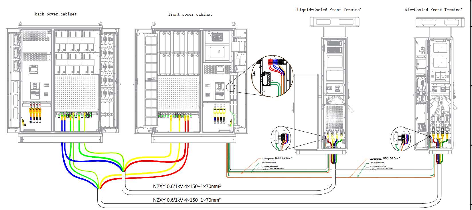
Power cabinet front busbar:
Power cabinet back busbar:
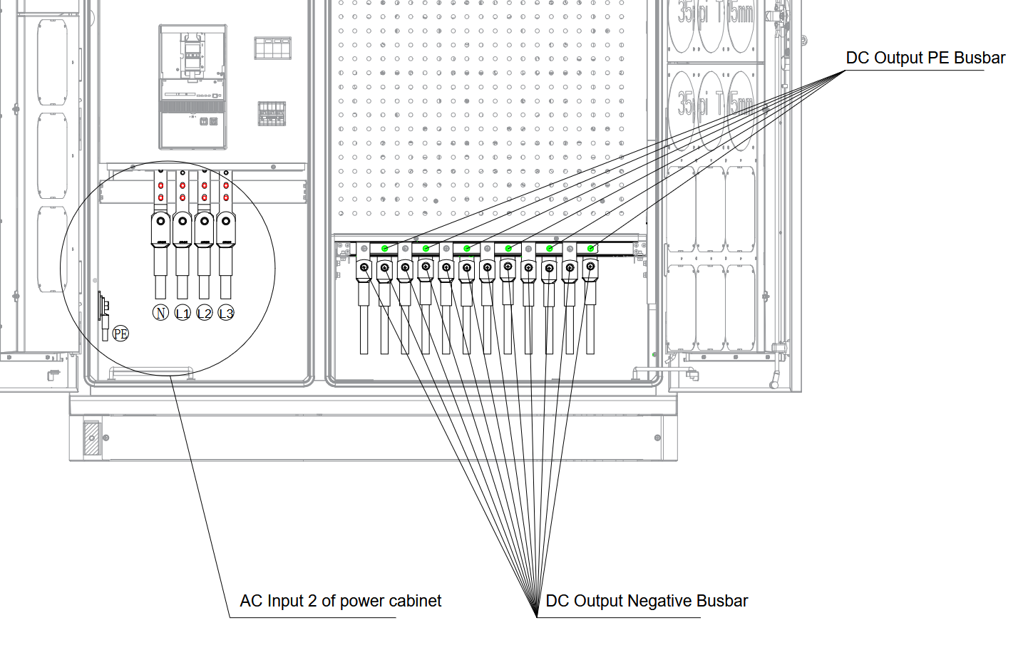
Negative busbar and PE busbar are separate but in parallel.
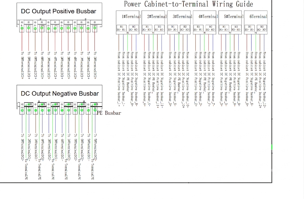
Busbar wiring guide into the satellite:
Ordered from most to least critical for safe, correct installation:
- Polarity / terminal identification (DC): At the front door the power distribution unit is the positive terminal; at the rear door it is the negative terminal. (Getting this wrong can damage equipment, so it is the highest priority.)
- Tightening torque for wiring screws:
- AC — L1, L2, L3, N phases: 31 N·m; PE cable: 15 N·m
- DC — DC output and PE cables: 15 N·m
- Use a torque wrench.
- Screw specifications:
- AC — M10×25 for L1, L2, L3, N phases; M8×25 for the PE terminal block
- DC — M8×25 for positive/negative output terminals and the PE terminal block
- Refer to the "Wiring Diagram" (480 kW cabinet) for AC and DC cable and terminal specifications.
- Seal cable entry holes with fireproof putty after wiring and installing the fireproof putty board (fire safety).
- Ground shielded signal cables nearby (DC).
- Separate power and signal cables with a minimum parallel spacing of 200 mm.
- Reserved cable lengths above the concrete surface:
- AC input cables: more than 700 mm
- DC output cables: more than 800 mm
- Communication cables: more than 1000 mm
- Door and protective-plate procedure: Open front and rear doors, remove the AC input / DC output protective plates for wiring, then reinstall the plates and restore the cabinet afterward.
Installation torque reference table:

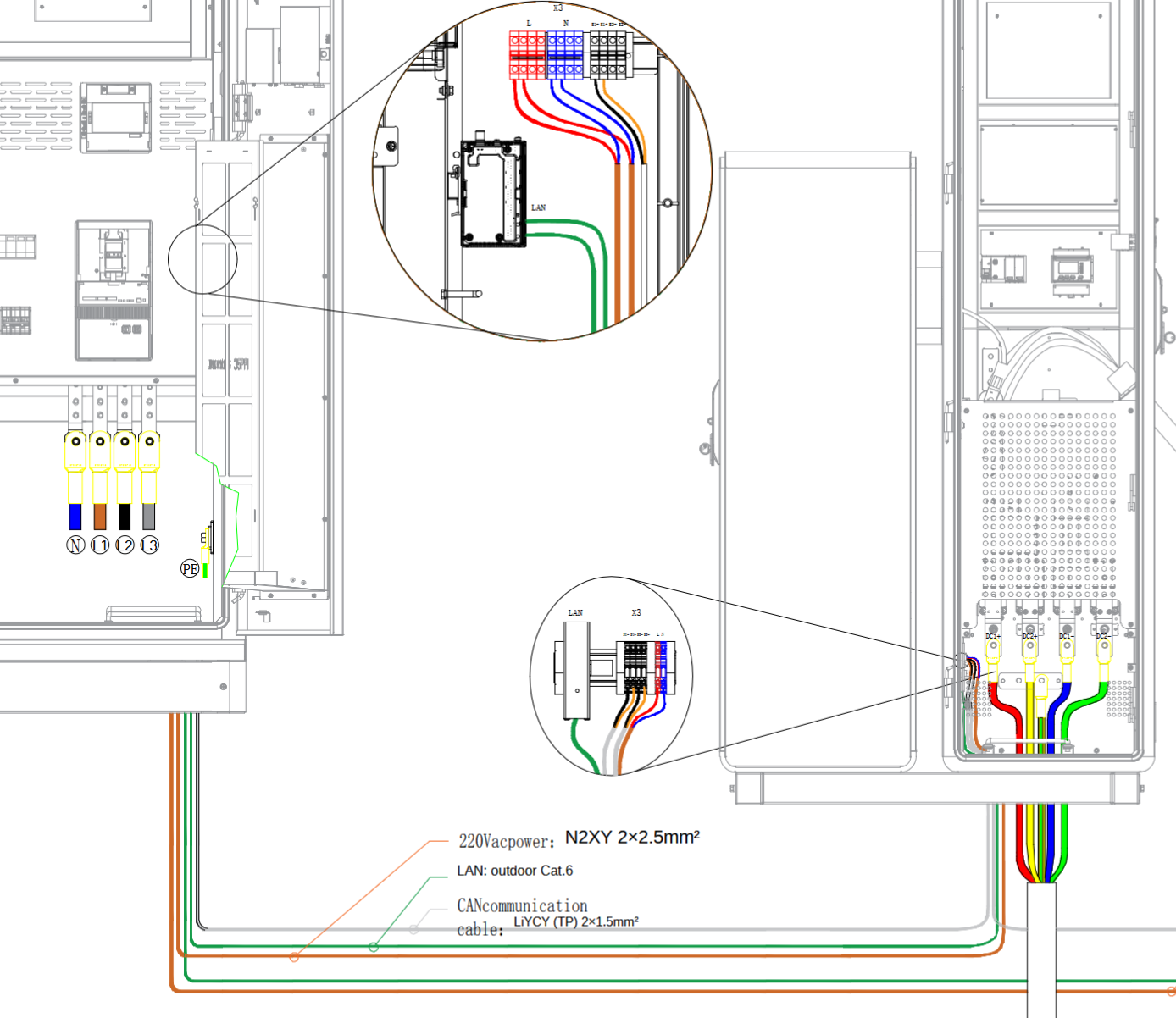
4.4.5.2 AC Input and Communication Wiring Diagram

4.4.6 Charging Connector Address Dialing
The charging connector address DIP switches must be set to the correct position for the connector to function. According to the station plan, set the address of this terminal connector and connect the DC input wiring A+, A−, B+, B− to the corresponding output busbar of the host, as per the table below.

The address DIP switches of the charging connector are shown below:

4.5 Power On
————————————————————————————————————————
![]() Danger:
Danger:
Use dedicated protective gear and insulated tools to avoid electric shock injuries or short-circuit failures.
————————————————————————————————————————
![]() Notice:
Notice:
- Commissioning is highly technical; commissioning personnel must receive the corresponding technical training and follow the commissioning instructions.
- Commissioning involves live work. Stand on dry insulating material, do not wear metal objects such as watches or necklaces, and use insulated tools.
- Avoid body contact with two charged objects at different electrical potentials.
- Before any closing operation, check that the status of the relevant units or components meets requirements. Measure the voltage at the front end of the breaker to confirm the input voltage is within the rated range.
- If others are not allowed to operate during the work, hang a prohibition sign on the distribution equipment: "Do not close the switch — work in progress."
- Observe while commissioning. If anything abnormal appears, shut down immediately and continue only after finding the cause.
————————————————————————————————————————
4.5.1 Power-On Procedure
————————————————————————————————————————
![]() Notice:
Notice:
Ensure all inspection results are "satisfied" before performing the power-on operations below.
————————————————————————————————————————
- Ensure proper connection. Verify that all cables (including to the host) are correctly connected, then reattach the power-compartment protection plate.
- Set breakers to OFF. Ensure both the AC input breaker and the host-side terminal power-supply breaker are OFF.
- Turn ON the host-side breaker. Set the host-side terminal power-supply breaker to ON, remove the front panel of the AC distribution breaker, and measure the voltage between terminals L and N of the AC input — it must be between 207 V AC and 253 V AC. Then reattach the panel.
- Turn ON breaker Q1. With the panel in place, set breaker Q1 to ON.
- Measure the output voltage. Measure the output voltage of breaker Q1 — it must be between 207 V AC and 253 V AC.
If you encounter any issues or have questions, please submit a ticket.
Was this article helpful?
That’s Great!
Thank you for your feedback
Sorry! We couldn't be helpful
Thank you for your feedback
Feedback sent
We appreciate your effort and will try to fix the article